Install Remote Unit - YOSHIMASA
- Home
- Install Remote Unit
DISCLAIMER
Yoshimasa assumes no liability regarding the improper installation or misapplication of its products. It is the installer’s responsibility to check for proper installation. Under no circumstances will Yoshimasa be liable for any labor charged or travel time incurred during installation of its products. Damage caused by improper installation is the installer’s responsibility and Yoshimasa assumes no liability. The following instructions only set an outline for product installation.
ヨシマサは お買い求め頂いた製品に対して適切な設置を怠たったり、間違った使用をした為に起こるすべての責任を負いません。設置ミスのために生じた不具合は設置業者に責任があります。また、Yoshimasaはどのような理由であれ製品設置に際しての人件費及び出張時間の費用の支払い義務はありません。不適切な設置方法で生じた製品の損傷はそれを設置した業者に責任があり、Yoshimasaとは関係がないと考えます。以下の説明は設置に際してのアウトラインです。
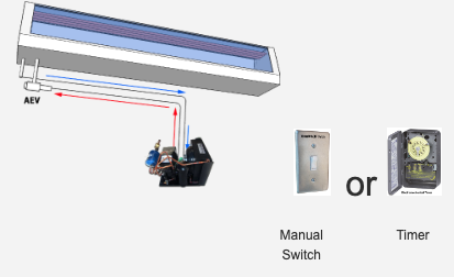
Single Unit (click picture to enlarge)
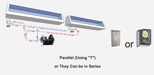
Multiple Units (2+) (click picture to enlarge)
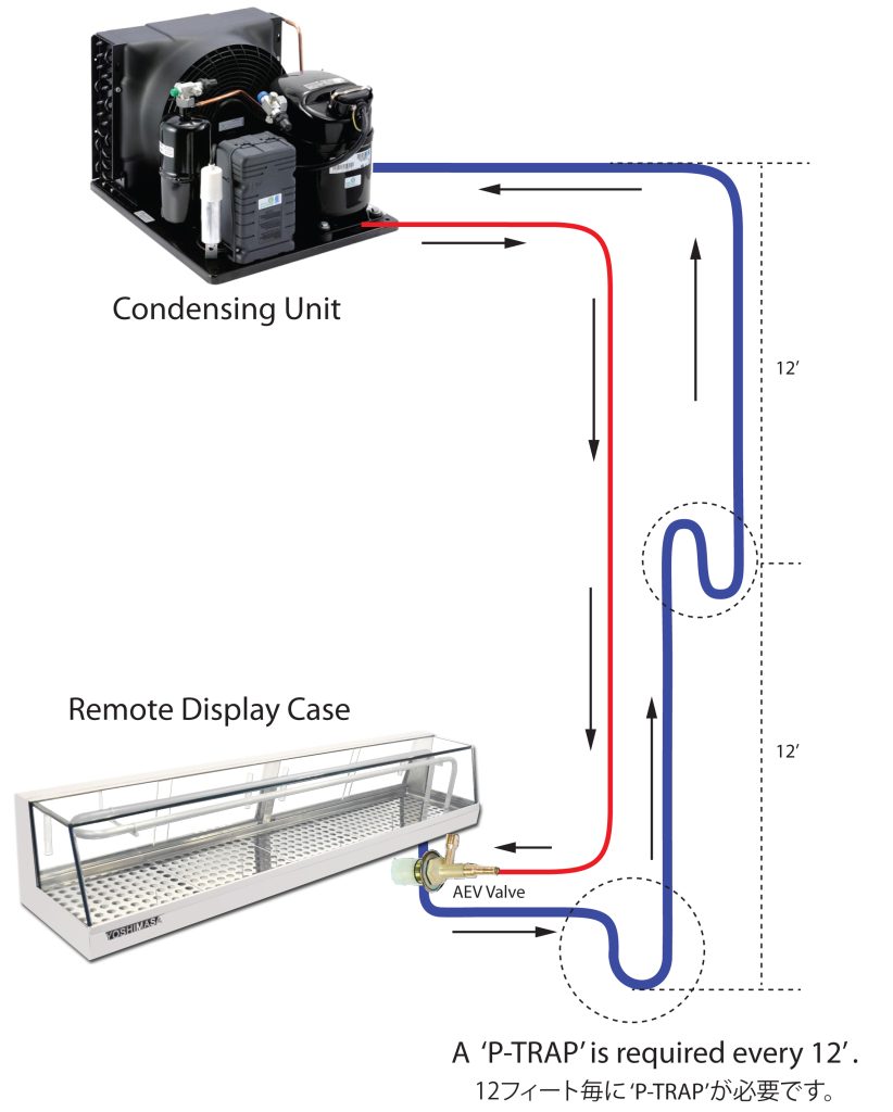
Install with 'P-Trap' (click picture to enlarge)
If a Condensing unit goes above the Display Case
Installation Guide
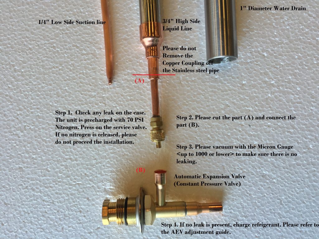
1. Please make sure there is no leaking by inspecting the service valve.
2. We regularly charge our units with 50-70 psi, so there should still be pressure inside.
3. Please do not install if there is no nitrogen in the case. Call YOSHIMASA Tech Support at (909)865-7111.
4. The 3/4” stainless steel pipe connecting to a copper coupling service valve is the liquid line (high side) and the 1/4” copper pipe is the suction line (low side).
5. Please do not remove copper coupling off the 3/4” stainless steel pipe.
6. While welding onto the copper lines, please cover AEV (Automatic Expansion Valve) with a wet towel or wet cloth. (DO NOT USE A TXV VALVE) Install the AEV at least less than 1-2 feet away. The closer it is the better.
7. Please use the Micron Gauge (up to 1000 or lower) to examine any possible leak before charging a refrigerant.
8. Please charge the refrigerant as a gas, not as a liquid. Don’t charge refrigerant until sight glass is full or you will have overcharged the unit. (You do not need to install sight glass). Simply charge the refrigerant until at least halfway down the suction line or until the entire suction line is frozen.
9. Do not charge the refrigerant by having container upside down. (The remote case does not have any labor warranty. Once the case is installed, we presume there was no leak present.)
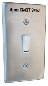
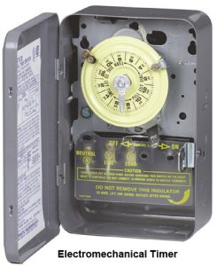
10. Please install a manual switch or timer since the sushi display case is not allowed to run for 24hrs.
11. Please install a solenoid valve or U-trap (at least every 12 feet) in case the compressor kit (condensing unit) is located above the sushi display case.
12. Please visit http://yoshimasausa.com/support/installre to find more helpful information to have a proper installation.
13. WARNING!!!
Sushi display cases are NOT allowed to run 24 hours. They are only meant to run at an ideal time frame of 8-14hrs maximum. They are not to be used for storage purposes, but only to display during business hours as per the health department. The compressor will get damaged, malfunction, or completely stop running which will result in having to replace it with a new compressor if there is continuous use going over the maximum usage limit of 18hrs. Please turn on right before business hour and turn off the case right after business hour and clean the cases. Any compressor damages from running over hours or 24 hour continuous running will not be honored by the warranty. In case the cases are used at a 24hr running restaurant such as a 24hr buffet restaurant, they still need to be turned off for at least 2-3hrs every 8-15hrs.
Before hooking up a Condensing Unit to YOSHIMASA Remote SUSHI Display Case, please follow the instructions below.
コンデンサーをヨシマサ寿司ネタケースに接続する前に下記の指示に従って下さい。
\
- WARNING – Click Here 注意事項
- Please handle with care and DO NOT let the INLET/OUTLET gas nozzles touch the ground directly. 扱いは十分注意してお願いします。ガスノズルの入り口と出口が地下に触らないようにしてください。
A Remote Unit has INLET/OUTLET gas nozzles at the LEFT BOTTOM for a C/U hook-up. Although they come sealed from the factory, there is NO GUARANTEE that they wouldn’t get any damage when mishandled. If this incident occurs due to your carelessness, the warranty shall be void and you shall hold full responsibility for it.
冷蔵無しの寿司ネタケースの左下にはコンデンサーへ接続するためのガスノズルがあります。工場から梱包されてきますが、間違って扱われると故障が無いとは保証できません。 注意して扱われなかったための事故には保証できませんので、ご了承願い致します。 - Please check and make sure GAS doesn’t LEAK! ガス漏れが無いか確認してください。
Every YOSHIMASA Remote Sushi Display Case comes with a certain amount of nitrogen gas (about 40psi) charged inside the evaporator tube from the factory. Thus, you should hear a short sound of gas releasing at the time of breaking the seal of either inlet or outlet nozzle caps. If you can’t hear any sound, which is a very rare case, but is possible due to imperfection of sealing the nozzle caps at the factory, you still cannot presume the case has a defect until you vacuum the evaporator tube for a actual leak. If any gas leak is found upon vacuuming please immediately contact YOSHIMASA Tech-Support at 1-800-789-9835 otherwise YOSHIMASA will presume that there has been no gas leak with the unit. If the unit has been installed without following the procedures described above, YOSHIMASA shall not be liable for any loss or damages of the unit from the installation.
全てのヨシマサ冷蔵なし寿司ネタケースには工場から(約40psi)のニトロガスが蒸発器の管に含まれてきますので、ガスノズルの入り口または出口のシールを外した際、短いガス漏れのような音が聞こえます。もし、工場でのシールが不十分なため何も聞こえない場合(まれですが)もありますが、蒸発器の管を真空にするまでは、欠陥があるとは推測できません。真空中にガス漏れを発見した場合、すぐにヨシマサテクニカルサポート 1-800-798-9835 までご連絡ください。連絡が無い場合、ヨシマサはお客様の寿司ネタケースには欠陥が無い物と称します。上記の手順を無視して寿司ネタケースを設置した場合、ヨシマサでは全ての紛失〔損失〕の損害賠償に責任がないものとします。 - Please have the Condensing Unit meet following recommended Horse Power (HP).
Since the job site circumstances can vary following information might not suit your situation. So, if you are not still sure we highly recommend you consult with a professional refrigerator technician. YOSHIMASA welcomes your call as well (1-800-789-9835). We also highly recommend you use an expansion valve to hook-up a Condensing Unit to the Remote unit. YOSHIMASA provides limited parts warranty only for a Remote Sushi Display Case 仕事の依頼状況がさまざまですが、プロの冷蔵庫専門家と相談してください。ヨシマサでもコンデンサー設置に関する質問等をお電話でも受け付けています(1-800-789-9835 。コンデンサーユニットに接続するために拡大バルブをご利用なさることをお薦めいたします。ヨシマサでは、冷蔵無し寿司ネタケースの部品の保証は限られています。

TOTAL SIZE OF SUSHICASE equals total length of YOSHIMASA Sushi cases sharing a compressor. 寿司ケースのトータルサイズはコンデンサーユニットを共有するヨシマサ寿司ケースのトータルの長さです。 | *Recommanded AEV: Parker’s AEV |
[ TECH. NOTES ] テクニカルノート
- Do NOT forget to measure the distance between the Sushi case and the Condensing unit and carefully choose the SIZE and TYPE of Compressor to get the appropriate temperature. (Please consult with the YOSHIMASA Tech. Team if you are not sure.) 寿司ケースとコンデンサーユニット間の距離を測り、その上で必要な温度を保つようコンプレッサーの種類とサイズをお選び下さい。(ご不明な点はヨシマサテクニカルサービスへご相談ください)
- Remember Overall Performance of Sushicase depends NOT ONLY on the components recommended above, BUT ALSO on your field Workmanship such as Leak-proof Welding, Amount of Refrigerant Charge, Proper Adjustment of Expansion Valve, and so on. 寿司ケースの全体的な性能は上記に推奨された構成だけでは無く、取り付け業者の技量、例えば密閉溶接、冷却剤、膨張弁の調節等様々な要素が関わってきます。
- All sushi cases are designed to operate in an environment of 78°F ambient temperature with 55% relative humidity.すべての寿司ケースは周囲の温度が77℉、55%の相対湿度の元での稼働を想定したデザインとなっています。
- Should you have any questions contact us and the YOSHIMASA Tech. Team would be glad to help you.ご不明な点がございましたらヨシマサテクニカルサポートまでご連絡下さい。いつでもご相談に乗ります。
COMPRESSOR APPLICATION CATEGORIES コンプレッサー運用カテゴリー
- Low Temp. : -40°F to +10°F: (-38度から-12度)
- Medium Temp. : -10°F to +30°F:(-23度から-1.1度)
- Commercial Temp. : -10°F to +45°F:(-23度から7.2度)
- High Temp. : +20°F to +55°F:(-6.6 度から12.7度)
- Air Conditioning : +32°F to +55°F+32°F to +55°F: ( 0 度から12.7度)
- Heat Pump : -15°F to +57°F:(-26度から13.8度)
AEV/AXV(Automatic Expansion Valve) or Constant Pressure Expansion Valve - AEV/AXV ( 自動拡大バルブ または 一定圧力の拡大バルブ)

AUTOMATIC EXPANSION VALVE GUIDE
The AEV (Automatic expansion valve) is closely resembled to the thermostatic expansion valve (TXV) and it operates in a different way.The AEV is called “Constant Pressure Regulator”. Its purpose is to maintain or keep constant evaporating pressure. As the pressure in the evaporator lowers, the valve opens and allows more refrigerant to flow through it. As the pressure increases, the valve closes and allows less refrigerant to flow through it. When turning clockwise, high side will go lower and low side will go higher (Evaporator temperature will go warmer). When turning counter clockwise, high side will go higher and low side will go lower (Evaporator temperature will go colder).
AEV/AXV Installation & Adjustment Instructions AEV/AXV設置と調整の説明
1. Valve Specifications バルブ仕様
- 0-90 PSIg adjustment range 0-90PPSlgの調整範囲
- Construction: Brass, copper and stainless steel 構造:ブラス、コッパー、あるいはステンレススチール製
- Internal equalizer イコライザー内臓
- UL recognized for maximum operation pressure of 500 PSIg high side, 225 PSIg low side ULで認証済みの最大圧力500PSlg、低いサイドで225PSlgの圧力がある製品
- Connections(inches): Inlet- 1/4 ODF, Outlet-3/8 ODF コネクション(インチ):差し込み口-1/4ODF,排気口-3/8ODF
2. Valve Orientation バルブの位置
The ideal position for installing the valve is in a draining position with the outlet pointing downward. However, the valve can be installed in any direction. Note the inlet and outlet of the valve as shown in Figure 1. バルブ設置の最適な位置は排気口が下に向くような位置付けです。しかし、バルブ自体はどの位置でも設置することはできます。 注記:Figure1の差し込み口と排気口の イン、アウトの位置をご参照下さい。
3. Valve Installation バルブの設置
For valves with copper to copper sweat connections, any of the commonly used types of solders, e.g., 95-5, Sil-Fos, Easy-Flo, Phos-Copper, Stay Brite 8, Blockade, or equivalents may be used. Regardless of solder type, the torch flame must be directed away from the valve body and the valve must be heat-sinked or wet-wrapped to avoid excessive heat on the valve and it’s internal components. See Figure 2.コッパー、及びコッパーの溶接部分は、一般のはんだ付け使用の物で大丈夫です。例:95-5、Sil-Fos、Easy-Flo, Phos-Copper, Brite 8, Blockadeフランド, 或いは同等の製品を使用してください。どのようなはんだ付けタイプにしても トーチの火はバブル本体から反対に向けてください。バルブはオーバーヒートすることとなります。その様な場合には濡れたタオルをバルブ本体に巻き付けることで熱さからバルブと内部の構成要素守ることができます。注記:Figure2
During installation, the valve must not exceed 250°F. Excessive heat applied to the valve could alter internal components and factory braze joints, leading to refrigerant leaks and faulty operation. 設置の際、バルブ本体へ250°F以上の熱をかけないでください。バルブに高い熱がかかると内部構成要素が変わってしまったり工場で真ちゅう付けされてあるジョイント部分の損傷またはそのことが原因となり、冷却剤の漏れそれに伴っての操作不良となります。
4. Valve Adjustment バルブ調整
All AEV/AXVs are factory set based on Customer reqirements. However, AEV/AXVs are adjustable using an adjustment knob or gland. See Figure 3. For AEV/AXVs, simply remove the protective plastic cap and turn the adjustment knob/gland clockwise to iincrease the outlet pressure set-point or counterclockwise to decrease the outlet pressure set-point.すべてのAEV/AXVは顧客要件に沿ったセットとなっています。しかし、AEV/AXVは調整ノブを動かすことによって設定を変えることができます。注記:Figure3. AEV/AXVの保護プラスティックキャップを外し、時計方向に回すと排気口への圧力が上がり、その反対方向に回すと排気口への圧力が下がるようセットされます。
When installing our remote units, we ask that you use a Micron Gauge (up to 1000 or lower) to examine for any possible leaks before charging any refrigerant. The remote cases are not covered under any labor warranty, since once the case has installed, we presume there was no leak present. If there are any leaks found after installation, we would not cover under warranty since you need to be checking for leaks at the time of installation.
リモートユニットを設置する際は、冷媒を充填する前に、Micron Gauge(最大1000以下)を使用して漏れの可能性を調べることをお勧めします。ケースが設置されると、リークが存在しないと推定されるため、リモートケースは労働保証の対象外です。インストール後にリークが見つかった場合、インストール時にリークをチェックする必要があるため、保証対象外となります。
* Please note that the control spring in these valves works with atmospheric pressure to move the valve in an opening direction. Any substantial changes in altitude after a valve has been adjusted will alter the low side flow rate maintained by the valve. If this data is required, please consult the Parker Engineering. 注意書き:バルブ中の弾力はバルブを開く方向へ移動する大気圧で動作します。バルブを設定後に大きな標高の変化があった場合、低い流出量を維持するよう変化します。もし、この件についての資料が必要な場合、パーカーエンジニアリングの方へご相談くださいませ。
5. Download – AEV/AXV (Automatic Expansion Valve) Installation Guide (PDF) ダウンロードして下さい。
